It takes inputs from the arduino i e.
Password based door locking system using arduino ppt.
Download the library for keypad h from below.
Lock the door by using password.
Password based door locking system project report pdf 16.
Password based door lock system using 8051 microcontroller ppt 15.
To give user more secure yet cost efficient way of door locking system.
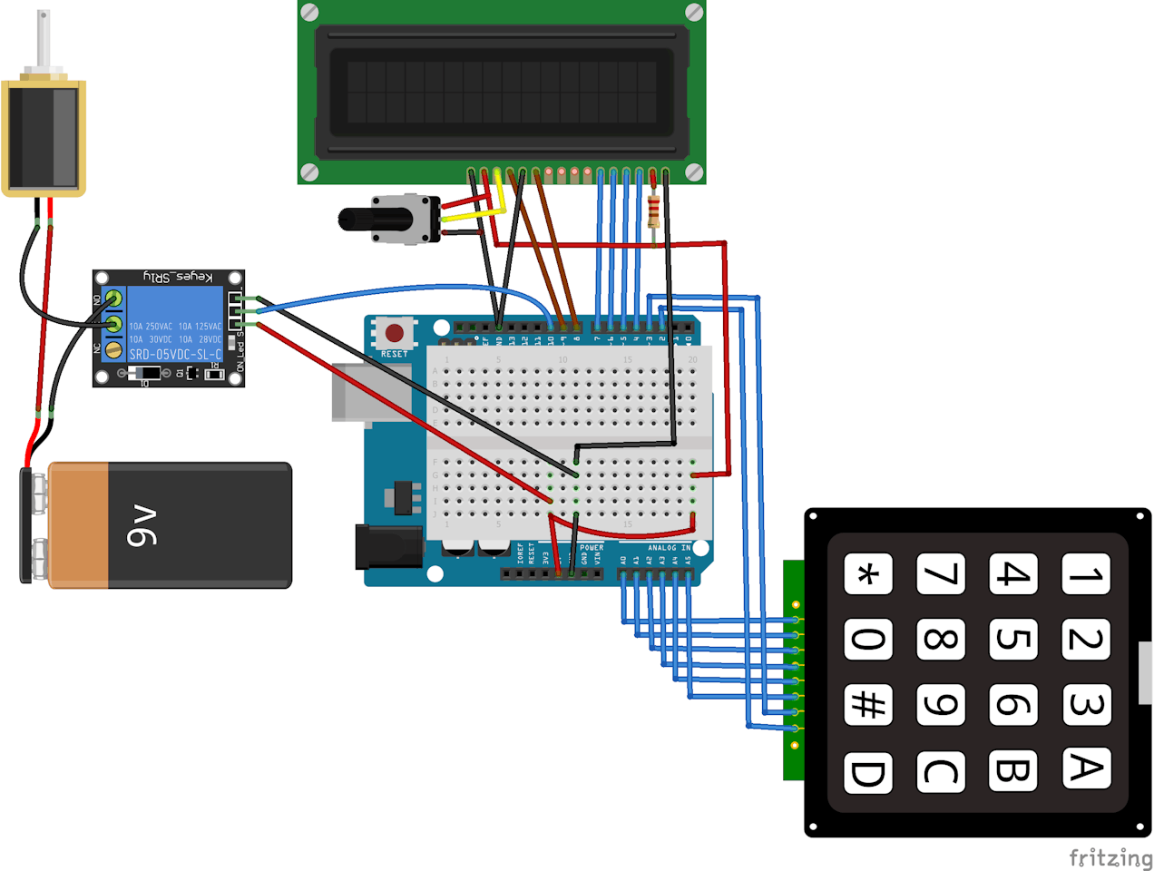
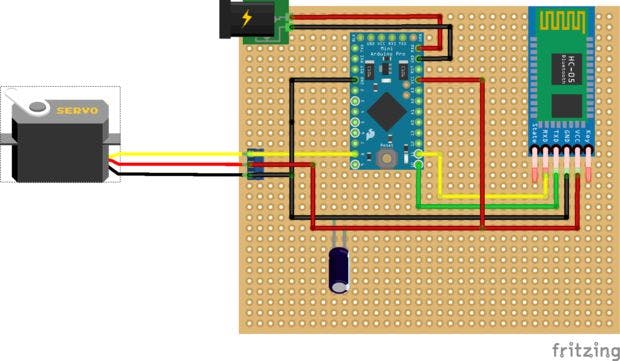
Pins 11 and 12 are connected to the inputs of the l293d.
Password based door lock system using arduino 14.
Give the flexibility to the user to change or reset the password in case the user forgets that combination.
It is a simple embedded system with input from the keyboard and the output being actuated accordingly.
Again if another person arrives it will ask to enter the password.
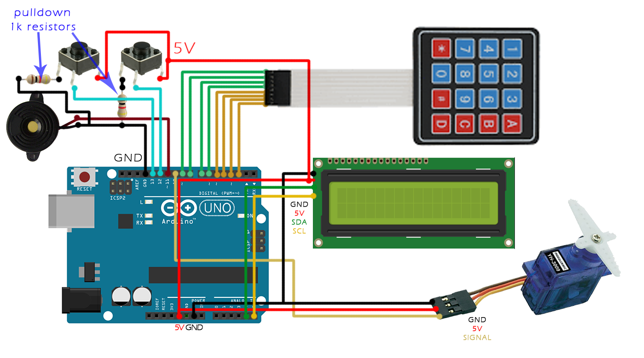
Password based door locking system the operation of this system can be described by the above block diagram which consists of blocks as keypad a buzzer an lcd a motor driver and a stepper motor.
Hence the actuator is pulled inside and the door opens.
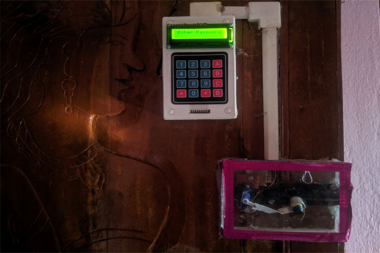
This circuit allows activation of an electronic door lock only on entering the correct password.
The simply compile it then finally upload it to the atmega328 microcontroller.
So when the password is correct pin 11 is set high and pin 12 is set low.
Objective increase the security level to prevent an unauthorized unlocking of the door.
5v input and outputs 12v to its output pins to which the actuator is connected.
It was an interesting project which required beginner s level skill in programming and very easy to connect circuit.
In countries like india such automatic systems are not cheap by any yardstick.
So we decided to test a simple and cheap prototype to see if such a robust system could be developed using the tool of our choice arduino uno.
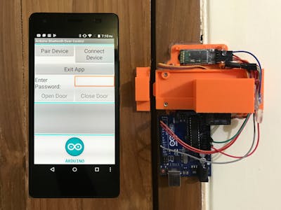
To open the door the user will have to first scan the right tag and then he will have to enter the correct password.
When we see sophisticated door management system s the price tag struck immediately along with the utility of course.
Just thought of making a password based door lock system in which you can enter the password via the keypad.
This block gives the entered code signals to the microcontroller.
Rfid and keypad based door lock using arduino by aqib.
Shown in video 3.
The keypad is an input device that helps to enter a code to open the door.
This system demonstrates a password based door lock system using 8051 microcontroller wherein once the correct code or password is entered the door is opened and the concerned person is allowed access to the secured area.
It is a keyless system where you can use your own personal code to enter your home with just a few simple pushes of some buttons.
The code for password based door lock security system using arduino keypad is given below.